Toyota Obd1 Serial Interface For Arduino
Arduino + CAN-BUS shield to monitor fuel consumption and other vehicle parameters. I first wrote this to get a fuel economy meter on my RX-8, and later worked to reverse engineer the messages streaming across the CAN-BUS to see what sensor data is available on the car.
Features:
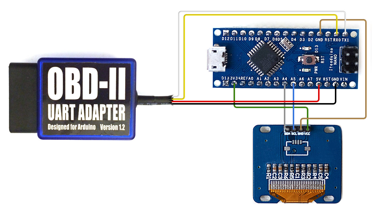
It provides you a serial interface using the ELM327 command se The basics of OBD-II commands How to hook this up to an Arduino and display information to an LCD. An arduino code that reads Honda OBD Protocol and translates it to ELM327 protocol. Hobd_lcd - implements Honda OBD to LCD display - not updated. UNI_wiring.png - Unified wiring diagram for arduino UNO (compatible). Oct 10, 2014 Hack an ELM327 Cable to Make an Arduino OBD2 Scanner. By mviljoen2 in. I will be removing the board from the ELM327 Enclosure and then bypass the USB bridge chip and attach the Serial TX/RX pins of the arduino to the Serial TX/RX pins onto the ELM327 board, program the arduino and attach the ELM327.
- Live streaming of CAN-BUS content over serial link to connected PC (with logging and viewing software on PC side)
- Computes fuel consumption/mpg and displays on attached serial LCD
- Dumps available OBD-II PIDs to microSD card
Table of Contents
- arduino-ecu-logger
Materials
- Arduino Uno
- [Serial LCD] (https://www.sparkfun.com/products/9394)
- CAN-BUS shield (includes a joystick and microSD slot)
- OBD-II to DB9 cable to connect between your car and the CAN shield
- microSD card
Arduino side
The Arduino can operate in one of four modes, selected on bootup using the joystick:
- (down): live vehicle stats. Show MAF-based fuel efficiency (mpg) and consumption (oz/hr) on line 1 of LCD; coolant temperature and throttle position on line 2.
- (up): CAN spy. Stream CAN-BUS frames over serial connection to attached PC for logging, reverse engineering, and analysis.
- (left): query ECU for supported OBD-2 PIDs and write to microSD card.
- (right): serial simulator. Send fake CAN-BUS frames over serial connection to test PC interface code.
Hardware pin connections are described in logger/README.
The PC interface uses a custom framing protocol for high-speed reliable transmission of CAN frames to the PC. Once every 127 frames, a synchronization frame is sent over the wire; each frame starts with a sentinel byte, and each frame is protected by a CRC8.
PC side
python/can-dumper.py supports reading CAN frames either from a serial-connected Arduino (python/arduino.py:ArduinoSource) or from an on-disk log (python/hdf5_log.py:HDF5Source), and can stream frames simultaneously to a number of outputs, including an on-disk log or a curses-based live display of different CAN-BUS addresses. A demo logfile is available to play with the viewer; run python can-dumper.py example_log.h5.
The curses interface is shown below:
The top two rows are a summary of the vehicle's current state, as inferred from decoding data on the CAN-BUS (see section below on the RX-8). Below that is a live-updating view of the last frame received for each CAN-BUS destination ID, including the rtr and data fields, as well as an estimate of the rate at which traffic is flowing to each ID. Following these fields as inputs are changed on a car (eg, throttle position, rpm, brake engagement, speed, steering angle) can help decode their meaning.

The RX-8 CAN
This blog post describes some reverse engineering of CAN messages from a Mazda 3; much of the data is the same on my Mazda RX-8, but not all. The spreadsheet in data/ (as well as the decoding logic in python/rx8.py) describe the CAN IDs that I have successfully mapped on the RX-8. HDF5 logs can also be plotted using python/plot_logs.py.